Overview of the HC-SR501 PIR Motion Sensor
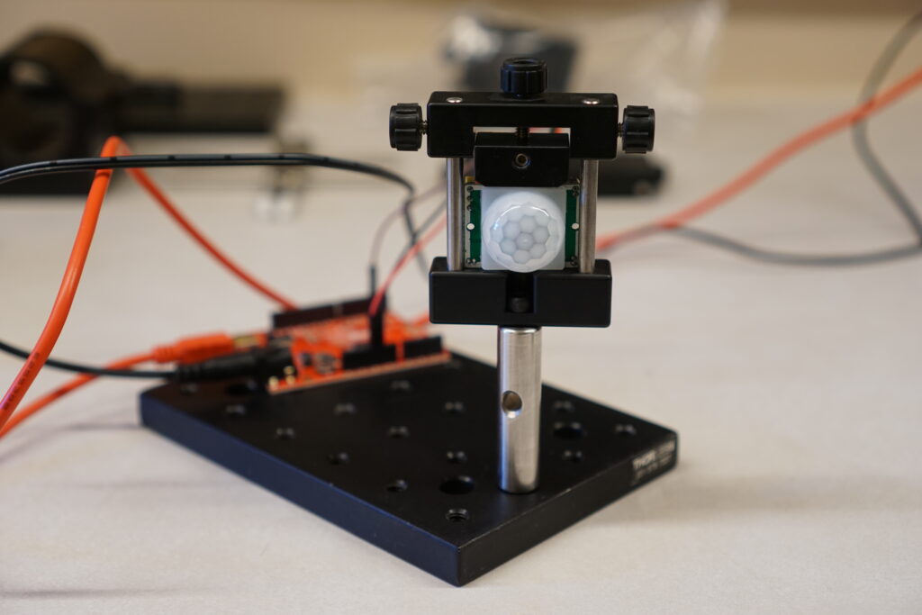
The HC-SR501 passive infrared (PIR) motion sensor is popular with Arduino enthusiasts due to its low cost, on-board controls, and customizability.

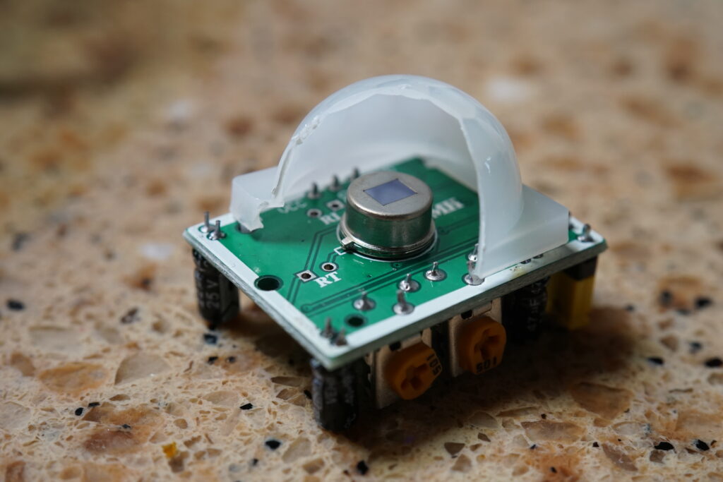
At the heart of this sensor are two pyroelectric elements inside a TO-5 can. The use of pyroelectric elements is fundamentally why this device is sensitive to moving thermal bodies and not static ones. Each element responds to changes in temperature by building up surface charge.

These capacitor-like sensing elements are connected in series with opposite polarity as part of a circuit. If both elements observe the same temperature change, no current flows through the rest of the circuit, so spatially-broad, background thermal fluctuations are ignored.
When a temperature change is detected by only one element at a time or more strongly by one element than the other, a weak analog signal is generated. That analog signal is amplified and converted to binary by additional electronics. This TTL output can be connected to the digital input of a microcontroller board so that an alarm plugged into the board (LED, speaker, etc.) is triggered whenever motion is sensed.
The Optics
The plastic dome lens is an array of lenslets, none of which are actually Fresnel, although Fresnel lenses are so often used for PIRs that any PIR lens is referred to as a “Fresnel”.
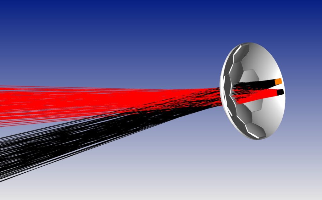
Based on my raytrace model below, each of these lenslets captures and focuses radiation onto one of the two pyroelectric elements from a field of view of roughly 30×60 cm at a distance of 3 meters.

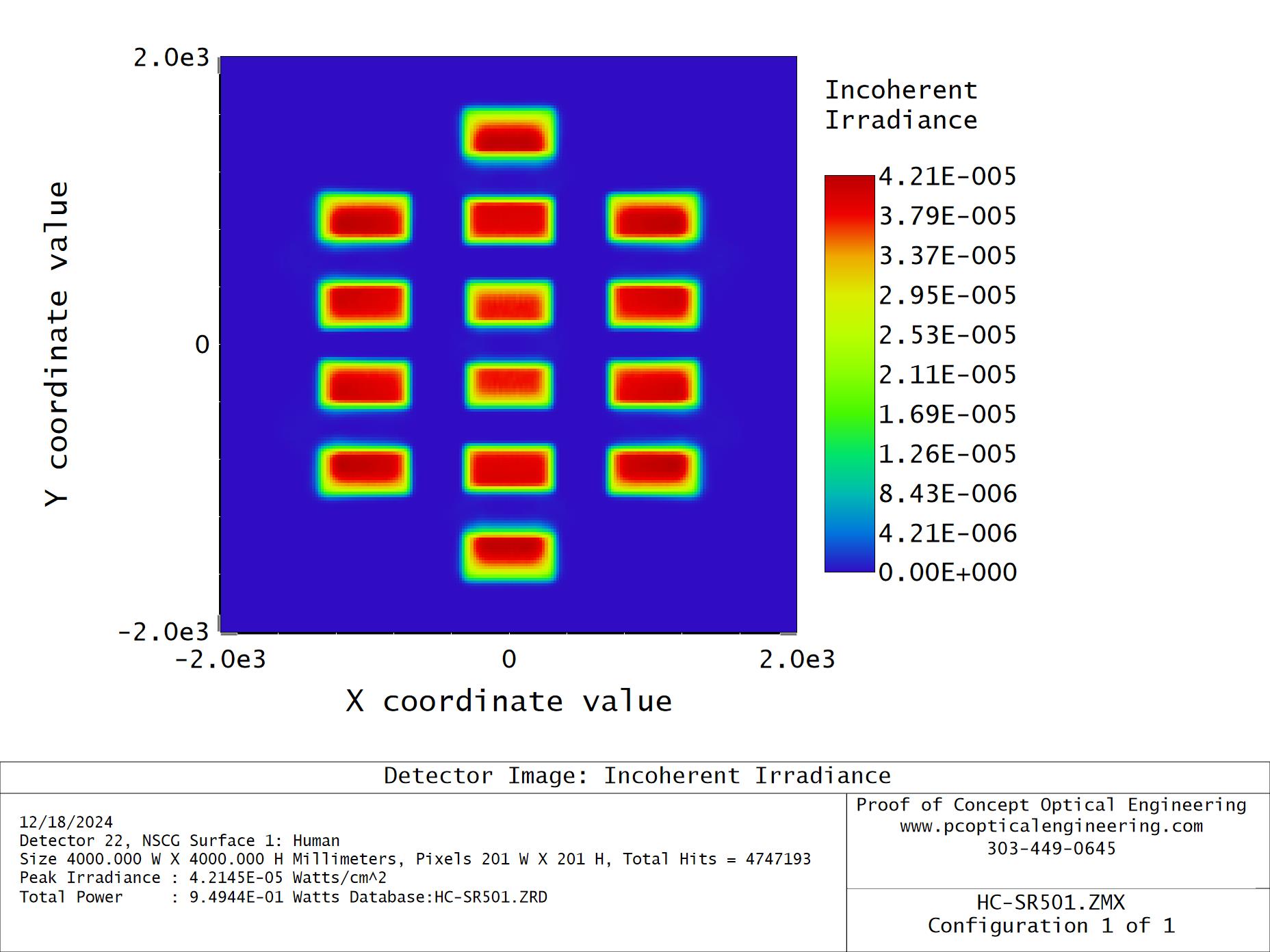
The use of many lenslets in a dome configuration gives the PIR its 110-deg overall field of view. The PIR doesn’t try to infer the location of motion. Instead, each lenslet monitors a distinct solid angle subtense and motion in any of these regions will trigger an alarm. The shapes and separations of detectable regions within the central field of view are shown below.

The HC-SR501 datasheet recommends orienting the sensor so the path of human movement is along the y axis in the figure above. A couple of reasons for that are evident. The aspect ratio of the rectangular regions along that path is a better match for a standing/walking person. Also, the two elements are sequentially activated as the person passes through the field of view of a single lenslet. If the path were along the x-axis instead, both elements would be activated simultaneously.
By activating both elements sequentially, a more reliable sensor response is achieved. From what I can gather, the resulting peak-trough waveform is interpreted by an on-board comparator as a much stronger, single signal than that generated by activating only one element.
Another consideration with PIRs is the range. At 3 meters, there’s ample separation between the fields of view as shown above. However, if you place the sensor much closer to the path, both elements can sense a passerby’s thermal radiation at the same time. That’s why the minimum recommended range is 3 meters.
Final Thoughts
Modeling this PIR in OpticStudio has given me a much clearer understanding of how PIRs work. I’ve documented my curious tinkering in this blog post to share what I’ve learned, as well as to demonstrate my ability to model optical systems in a way that’s meaningful. I hope you’ve enjoyed reading it and will keep me in mind for your next project.
Leave a Reply
You must be logged in to post a comment.